It
has been observed by various researchers since the turn
of the previous century that oxide films on metal anodes
can be rectifying. It has also been observed that a glow
discharge can appear on the anode. (1)(2) What this glow
is and why it occurs remains an open question.
NewCandle
list member Nick Reiter began publishing some preliminary
reports of this phenomena on list, and list member Horace
Heffner has published some experimental results and theories
regarding this phenomena as a potential source of new
energy (3)(4). I decided to do a few experiments myself,
to better understand the effect.
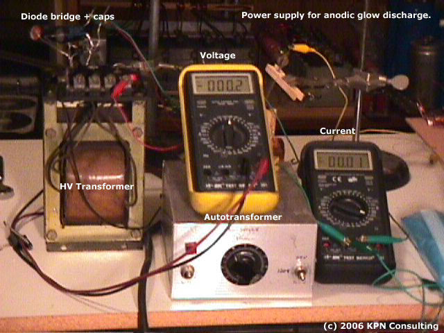
Power
Supply
The
power supply is an autotransformer driving a high voltage
transformer with a diode bridge and about 8 microfarads
of capacity to smooth the output. A 100 ohm resistor provides
some current limiting but is usually unnecessary due to
the high cell resistance. The resulting DC supply is capable
of about 1KV ( limited by the smoothing caps ) and is
unregulated but due to the large resistance of the cell
is basically constant voltage. Current and voltage are
monitored using B&K 391 RMS multimeters.
It
is possible to achieve a better current regulation with
this setup by increasing the series resistor and applied
voltage on the transformer taps. It is also possible to
achieve a quasi-constant current by monitoring the current
meter and occasionally adjusting the autotransformer.
Far better would be a true AC/DC constant current power
supply, if anyone out there has a Kepco BOP they don't
need I have a nice home for it here (grin).
Discharge
Cell
The
anode part of the cell is the base of a beverage can,
a concave polished aluminum surface that is a good shape
for controlling electric field gradients. The cathode
is a shaped carbon or aluminum rod. The electrolyte varied
depending on the experiment, but for much of the initial
work it was 50% citric acid in distilled water.
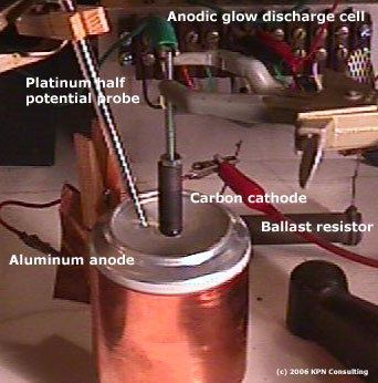
Voltage
could be monitored from either anode or cathode to the
solution with the platinum probe shown to the left of
the cathode.
Anodic
Glow Discharge
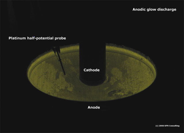
The
following picture was taken of this cell running at 210V
at 2 milliamps DC using 10% citric acid as the electrolyte.
The cell was conditioned for about 1 hour prior to the
photo. Note the difference in light intensity based on
the aluminum/aluminum oxide surface roughness. The color
is pretty much how it looked to the eye, greenish yellow.
The
voltage drop from cathode to solution was < 1.5 volts
at a 400 volt anode/cathode drop. The drop across the
electrolyte was <1 volt from the rim of the anode to
the cathode. Its fair to say that for concentrated electrolytes
almost all the voltage drop is across the anode. That
means the bulk of the input energy will be deposited directly
into the anode.
When
the voltage surpasses a certain point arcing from the
anode metal to the solution begins to occur. This process
happens at the weakest points first, in the case of the
cup anode along the rim where the electrolyte solution
and cup edge meet. Arcing can be prevented by growing
a solid and uniform oxide layer, and taking care to control
the region of interface between the air,anode,and electrolyte.
A film of inert oil can also control arcing at the air/electrolyte/anode
interface, but ultimately arcing from the anode directly
to the solution will prevail.
For some electrolytes strong
current densities are required to achieve anodization.
Given the small volume of electrolyte in this experiment
my conditioning currents were typically limited to 10's
of milliamps. With only a few watts entering the cell
the anode is kept cool and a good oxide layer forms.
The
less porous the oxide layer, the lower the current for
a given voltage when operating the anodic discharge. I've
been able to achieve 400 Volts at 2 milliamps with this
setup using 50% citric acid solution, and about 800 Volts
using concentrated boric acid. These are representative
values and points much high can be achieved with care.
Ultimately arcing will occur directly from anode to cathode,
when the voltage is sufficient. I've experimented with
this form of discharge (called water arc in the literature)
and it can be remarkably destructive to the electrodes
(I've vaporized tungsten buttons with one discharge event).
Here I'll stick to the glow...
The
glow brightness doesn't seem to improve greatly as you
increase voltage, rather it's the current/power that determines
brightness and to some degree color. This suggests
to me that the formation of the oxide layer is directly
responsible for the glow. I can increase the voltage,
see a temporary increase in brightness, then a decrease
as current diminishes. Also, going from 200 volts to 400
volts didn't seem to make all that much difference in
brightness, at 2 milliamps for both voltages.
Bearing
that last point in mind, it would probably be best to
operate this cell using AC with a DC bias or make a cell
with both electrodes of aluminum and use AC.
Next
page
Research
home page | Next page
References
(1)
http://www.sas.org/E-Bulletin/2001-11-16/chem/column.html
(2)
http://home.earthlink.net/~lenyr/borax.htm
(3)
http://www.mtaonline.net/~hheffner/BlueAEH.pdf
(4)
http://www.mtaonline.net/~hheffner/GlowExper.pdf