|
Research
home page
Arc
Oscillator
Oscillations
in arcs have been observed since the turn of the 19th century,
most notably by the Danish engineer Valdemar Poulsen. Generally
such oscillators take advantage of the differential negative
resistance characteristic of an arc. That is to say, the
arc voltage drop is roughly fixed, so that greater currents
passing though the arc produce lower resistance. This instability
in resistance makes it possible to transfer energy from
the arc to a resonant circuit. Oscillators based on this
property tend to be very harmonic rich, and have unstable
characteristics. They also tend to be inefficient.
In
the course of studying spark gaps, I observed a few basic
properties that lead me to conclude that an oscillator could
be designed in a much more direct and efficient manner.
Those properties were as follows.
- At
a given static voltage, a spark gap breaks over and the
resistance drops from a very high value to a low one.
- At
a given dynamic voltage, a spark gap will break over,
at a value lower than the static breakdown voltage. This
is called the restrike voltage.
- A
spark gap stops conducting when the current through the
gap reaches a very low value.
So
let's see how we can put those properties together to form
an oscillator. Here's a circuit diagram of my oscillator.
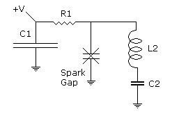
C1
and R1 form a power supply for the spark gap. C1 is very
large compared to C2, in my case about 10 microfarads. R1
established the effective impedance of the power supply,
about 250 ohms here. The spark gap is a pair of thoriated
tungsten rods in air, adjustable so that a good breakover
voltage can be established within the range of the circuit
components. L2 and C2 form the resonant tank circuit of
the oscillator, and those values are chosen to given a particular
frequency at an impedance very close to the resistance R1.
That is to say, sqrt(L2/C2) ~= R1. L2 is a single layer
wound on a ferrite core forming a high Q low distributed
capacity inductor.
Here's
a picture of the complete apparatus.

That
thing to the right is a home-brew HV DC power supply, using
a microwave oven transformer, diodes, and capacitor. Voltage
probes are positioned to show the voltage across the spark
gap on channel 1, and the voltage at the center of the resonant
tank circuit on channel 2. The spark gap is the white tube
in the center with the hex nuts.
The
circuit is operated by charging the cap to the breakover
voltage of the spark gap. The oscillograph below shows the
first few cycles of oscillation that ensue.

The
gap fires at about 620 volts, as can be seen from the initial
value on channel 1. As the gap begins to conduct, the tank
circuit discharges, producing a counter current in the gap.
When the tank current reaches peak value the current exactly
matches the DC current from the arc power supply and the
gap turns off. The voltage across the gap then rises, limited
by the value of inductance in the tank. In this circuit,
at this frequency, the restrike voltage is 376 volts. When
the restrike voltage is reached the gaps fires again and
another cycle of oscillation occurs. This process continues
until the voltage on the power supply cap drops below the
restrike voltage as shown in this scope shot.

Note
that the roughness of the traces is due to the limited scope
sampling rate at this timebase. None of that modulation
exists in the real signal as can be seen by using the second
timebase to magnify portions of the base signal. Remember,
scopes can lie! What is true is the starting and ending
voltages, and the time of total discharge, about 3 milliseconds.
The oscillating frequency is 500KHz.
Were
this circuit powered by a DC supply capable of supplying
enough power at the rated voltage, you'd have a continuous
RF oscillator. Such a circuit would need some kind of cooling
for the gaps as they would have to dissipate heat that can
be safely ignored in this pulse circuit. The circuit can
be made to work over a broad range of values. At the low
end, frequencies below about 10 KHz have restrike voltages
close to the DC value, making it difficult to achieve stable
and harmonically pure oscillation. At the high end, the
restrike voltage becomes very low and construction of the
tank circuit can be challenging. But in principle very high
frequencies can be attained.
|